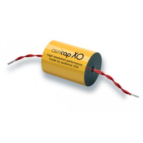


Capacitor Auricap XO 2.2R uF 10% 200V
Axial, solid-core wires for PCB

Auricap XO precision wound high resolution metalized polypropylene capacitors, made by Audience U.S.A. Specializing in OEM service for the finest designs.
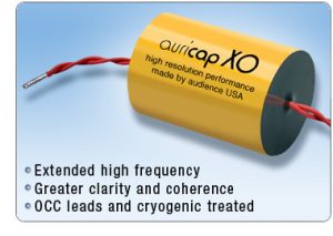
Auricap XO is a new high performance capacitor product from Audience that is the result of rigorous consideration of every aspect in capacitor design and the manufacturing process. Audience has reconsidered a host of parameters including tension windings, baking times and cryogenic treatment among other proprietary procedures. Auricap XO is made using the very finest obtainable polypropylene film and new high purity continuous cast copper leads. This new capacitor design offers reduced parasitic such as ESR improving on its effective bandwidth, clarity and coherence. With these design changes a new level of performance is reached with even less coloration, micro-phonics and noise contribution than the famous Auricap. There are no drawbacks to the Auricap XO in comparison to the standard Auricap. Users can still expect all of the wonderful virtues for which the standard Auricap is known. In brief, the Auricap XO is simply more transparent allowing you to hear farther into the music.
Auricap metalized Polypropylene capacitors are cylindrically wound with epoxy end fill and have very good volumetric efficiency. They are wound to exacting industry leading specifications to meet or exceed the requirements of MIL-C-55514A and MIL-STD-E method 103B.
As with all metalized polypropylene film capacitors Auricaps are self healing. Failure mode is as an open circuit. Auricaps are made with the very best film available and are constructed to center value. Special care is taken to insure industry leading ESR values.
Auricaps are designed to be a general purpose capacitor for use in all applications where size, value and temperature considerations are suitable. They are useful in signal coupling, filtering and power factor correction applications. They are available in matched sets as well as 1% tolerance as a special order.
Auricaps are available in axial and radial hard lead configurations for printed circuit board use. «R» means Radial with solid core wires for PCBs
Auricap Metalized polypropylene capacitors are rated for use in the temperature range from -55 to +85 deg. C and derate to 60% of their voltage specification at 105 deg.C. Auricaps are proven to have industry leading reliability and are 100% tested to meet specifications
Auricap XO lead wire is Auric OHNO "mono crystal" hook up wire, with XLPE insulation. Audience sells this sensibly designed, down to earth, easy to work with, natural sounding hook up wire. Auric wire is made of soft high purity stranded copper; each strand individually polished for better electron flow. The insulation is high quality cross linked polyethylene that resists shrinking when soldered. The polyethylene insulation has good dielectric properties, close to Teflon, so it sounds very good.
LEADS
Auricap film capacitors are not polarized. However, Auricaps have an outside foil (side of capacitor marked with black dot) that is a very useful noise shield when input and output impedances are considerably different values and it is connected to the lower impedance. The outside foil connection of Auricaps is identified with either a black lead (when leads are red and black) or a shorter lead when leads are solid core type. This identification is not a voltage polarity indication but is a consideration for minimum noise pick up.
Audience do not mark lead wires anymore!
1) In all coupling applications the input to the Auricap should be the outside foil and connected to the signal source or circuit output with the opposite lead/inside foil continuing on to the next circuit input.
2) In all power supply decoupling applications the outside foil should be connected to ground and the opposite lead/inside foil connected to the voltage to be decoupled. This is true for decoupling either voltage polarities.
3) In loudspeaker crossover applications, if the Auricap is in series, like feeding a tweeter, the outside foil connects to the input binding post and the opposite lead/inside foil connects to the tweeter. Where the Auricap is in parallel, as typically used for woofers, the outside foil connects to the speaker connection that connects to the input binding post and the opposite lead/inside foil connects to the other speaker terminal. Follow these same rules for midrange connections where you will have a combination of both.
The idea is to always have the outside foil connected to the lower impedance to provide outside foil shielding to noise. Circuit outputs are always lower impedance than inputs and should be connected to the outside foil.
Auricaps will blossom during the first 50 hours of use as they break in for most applications. At first they will be a bit stuffy so please be patient to allow for the magic of these high quality audio grade capacitors to unfold. However, for use in electric guitars, for example, the signal level is so low it could potentially take years for break-in.
To greatly expedite the break-in of capacitors a 30v AC transformer of 25 watts of more can be used across the cap (out of circuit of course) for a minimum of 100 hours. For quicker break in a 60v transformer can be used or a minimum of 50 hours. It is okay to break in capacitors of differing values simultaneously with the transformer. It is also okay to break in large quantities of caps simultaneously.
BYPASSING
Do not use bypass capacitors in the signal path. A single capacitor for DC blocking/AC coupling creates a simple path with one time constant. The signal quality will be compromised if a bypass or multiple bypass capacitors are added to a signal path capacitor. Bypass capacitors were used in the past to bypass low quality film capacitors or electrolytic capacitors. The bypass was the lesser of two evils. With the advent of better quality film capacitors the need for a bypass capacitor was eliminated. Bypass capacitors create multiple signal paths with multiple time constants. These time constants are very short but they can still be heard as a smear or overall loss of focus.
Always bypass power supply capacitors. This maintains a low source impedance to the power supply over a wide bandwidth. If budget and space permit it is good to use multiple value power supply bypass capacitors with the smallest value being installed directly at the active device. (Tube or transistor.)
| DC VOLTAGE | EQUIVALENT VAC (RMS) RATINGS AT | |||
| RATING | 60Hz | 400Hz | 800Hz | 1200Hz |
| 200 (.00 μF through 1.0 μF) | 160 | 120 | 80 | 60 |
| (1.1 μF through 5.0 μF) | 120 | 90 | 60 | 50 |
| 400 (.001 μF through .82 μF) | 240 | 180 | 120 | 90 |
| (.83 μF through 4.0 μF) | 210 | 157 | 105 | 78 |
| 600 (.001 μF through .47 μF) | 504 | 280 | 240 | 90 |
| (.23 μF through .82 μF) | 415 | 230 | 195 | 74 |
| (AC voltage assumed to be sine wave) | ||||
Sinu ülevaate hindamise saatmine ebaõnnestus
Teavita sobimatust kommentaarist
Teavitus on saadetud
Sinu teavitust ei saa saata
Kirjutage oma ülevaade
Ülevaade on saadetud
Sinu ülevaadet ei saa saata

Capacitor Auricap XO 2.2R uF 10% 200V
Axial, solid-core wires for PCB
check_circle
check_circle
